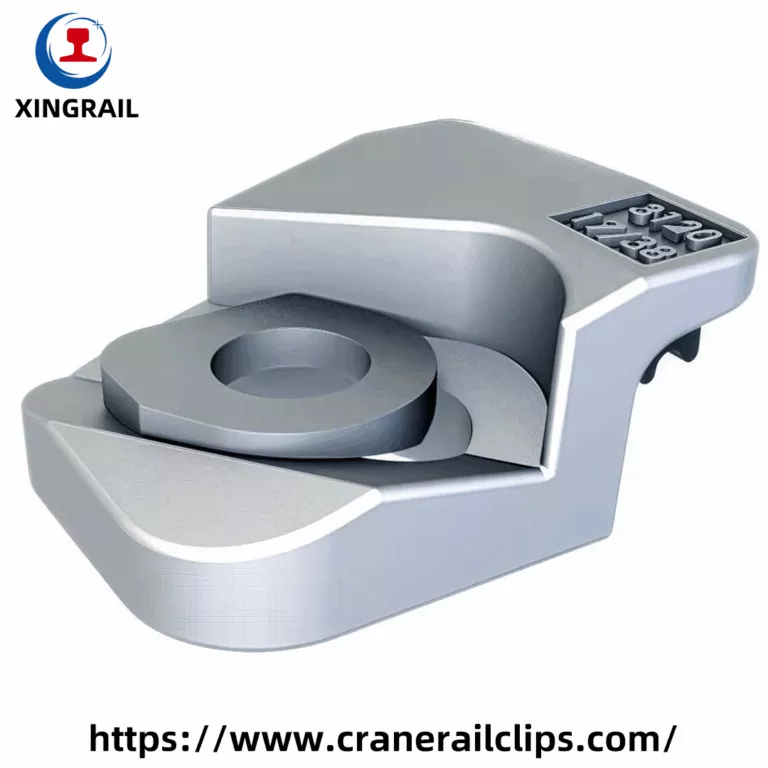
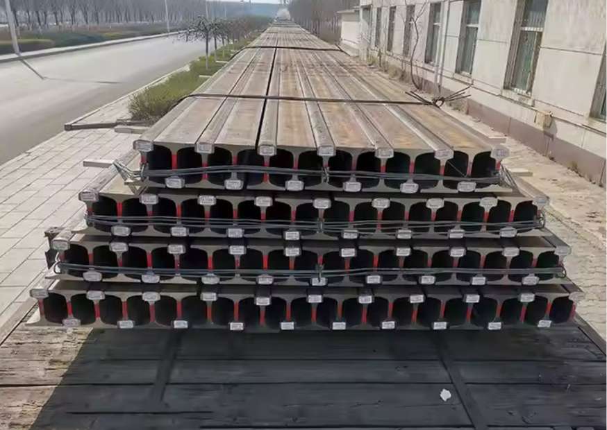
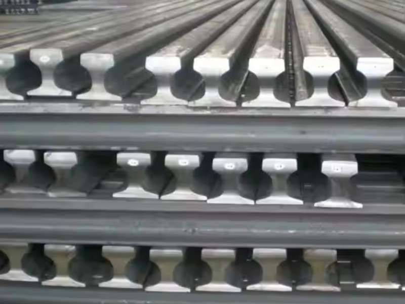
A crane rail clip is chosen on seven hard numbers: rail foot width, hold-down force, lateral load capacity, adjustment range, fixing method, material grade, and coating class. Match all seven and the rail stays true for decades. Miss one and you get rail creep, loose fasteners, uneven wear, and wheel flange damage inside the first year. Below is crane rail clip specifications means in practice, and how to read it off a datasheet before you place an order.
Rail Foot Width and Profile
This is the first filter. A clip jaw sits on the rail foot, so the foot width and the foot taper have to match the clip geometry.
Crane rails fall into a few families. DIN 536 A-series rails (A45 through A150) have wide, thick feet. ASCE and light rails such as 30 kg/m or 50 kg/m have thinner, more sloped feet. UIC 54, UIC 60 and QU100 sit somewhere in between.
A clip made for a 150 mm foot will not clamp properly on a 100 mm foot. It may hold at first, then work loose under cyclic load. Always confirm foot width in millimetres, not just the rail name. Two rails with similar names can have different feet. Our rail dimensions library lists foot width, head width, and height for the common profiles.
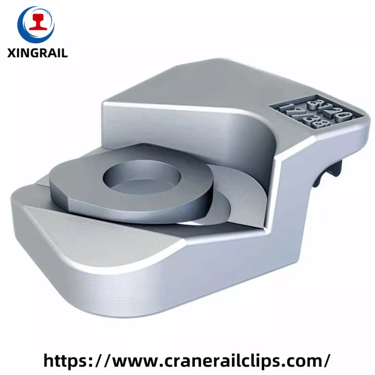
Rail Weight per Metre
Rail weight tells you how much load the runway is designed to carry. Heavier rail usually means heavier wheel loads, and heavier wheel loads mean higher uplift and side thrust at the fastening points.
A 150 kg/m crane rail under a ship-to-shore crane needs a very different clip from a 24 kg/m rail under a small workshop gantry. Weight per metre also affects clip spacing. Check the figure against the rail weight complete guide before you size anything.
Hold-Down Force
Hold-down force, sometimes called clamping force or vertical restraint, is the load the clip applies downward onto the rail foot.
Why it matters: as a crane wheel approaches, the rail ahead of it lifts slightly. If the clip cannot hold that uplift, the rail pumps up and down thousands of times a day. Pads crush, welds crack, bolts back off.
Datasheets normally quote force per clip in kN. Compare like with like. Some suppliers quote per clip, others per pair. Ask which. Also ask whether the figure is initial installed force or the force retained after 10,000 load cycles. Forged clips with a spring element hold their force far better than plain rigid plates.
Lateral Load Capacity
Side thrust comes from crane skew, crabbing, wind, and gauge deviation. On outdoor port cranes it can be very high.
The clip has to resist that horizontal push without permanent bending. Look for a stated lateral capacity in kN per clip, and check whether the number refers to elastic limit or ultimate failure. Elastic limit is the useful number. Once a clip yields, alignment is lost and it will not spring back.
For heavy lateral loads, a positive mechanical stop is better than friction alone. Serrated interfaces, keyed bases, and welded stop plates all help.
Adjustment Range
Runway beams are never perfect. Concrete moves. Welds shrink. Gauge drifts.
Adjustable clips let you shift the rail sideways after installation, usually ±10 mm to ±20 mm depending on the model. This is done with eccentric washers, serrated plates, or slotted base holes.
Fixed clips are cheaper and fine when the substrate is machined steel and tolerances are tight. Adjustable clips pay for themselves on long runways, on concrete, and on any track that will need re-alignment during its life.
Welded or Bolted Fixing
Both work. They suit different situations.
Welded crane rail clips attach directly to a steel runway girder. No drilling, no anchors, fast installation, very high pull-out strength. The trade-off is that repositioning means grinding off the weld. They suit steel structures where the rail position is settled.
Bolted crane rail clips use anchor bolts or through-bolts. They can be loosened, shifted, and re-tightened. They suit concrete beams, floor-mounted tracks, and any project where later adjustment is expected. Bolt grade matters here. Grade 8.8 is common, 10.9 for high-load applications.
Whichever you pick, confirm the weld throat size or the bolt torque value in the installation sheet. Under-torqued bolts are the most common cause of clip failure we see in the field.
Related: polar crane rail fastening systems with EN 10204 3.1 documentation and Q355B forged bodies.
Material and Heat Treatment
Forged steel outperforms cast iron for this job. Forging aligns the grain flow and gives better fatigue life.
Ask for the steel grade, the heat treatment condition, and the hardness range. Quenched and tempered medium carbon steel is typical. Yield strength should be stated. For clips with a spring function, spring steel such as 60Si2Mn or 38Si7 is used, and the hardness window is narrow. Too soft and the clip relaxes. Too hard and it cracks.
Corrosion Protection
Match the coating to the site.
- Indoor workshops, dry conditions: zinc plating or black oxide is enough
- Outdoor yards, general industry: hot dip galvanizing
- Ports, coastal terminals, splash zones: hot dip galvanizing at higher thickness, Dacromet, or epoxy
- Chemical plants and smelters: specify by exposure category
Bolts and washers need the same protection level as the clip body. Mixing a galvanized clip with a plain steel bolt gives you a rusted bolt head and a very unhappy maintenance team.
Rail Pad Specification
Most crane rail clips work with an elastomer or HDPE pad under the rail foot.
The pad spreads wheel load, absorbs impact, cuts noise, and takes up small surface irregularities. Typical thickness is 6 mm to 10 mm. Check the Shore hardness and the temperature range. Standard rubber degrades near a steel mill furnace bay. Silicone or high-temperature compounds are used there.
Pad width should match rail foot width. An undersized pad concentrates stress and tears.
Clip Spacing and Quantity
Standard spacing is 500 mm to 750 mm, with 600 mm as the usual default. Closer spacing raises stiffness and is used for heavy wheel loads or where the substrate is uneven.
Clips are installed in pairs, one each side of the rail. So a 100 metre runway at 600 mm spacing needs roughly 334 pieces.
Rather than working this out by hand, use the configurator below. Pick the rail category, pick the rail model, enter the single track length, then hit Calculate & Find Clips.
It returns matching fastening solutions and an estimated quantity based on 0.6 m spacing, installed in pairs.
Standards and Test Documentation
Ask which standard the clip is built and tested to. Common references include DIN 536 for rail profiles, EN 13674 for rail steel, AREMA for North American practice, and GB standards in China. Crane structure codes such as FEM and CMAA set the load cases the fastening has to survive.
Request the material certificate, the dimensional inspection report, and the load test data. A supplier who cannot produce these is guessing. Our rail standards reference covers the main regional systems side by side.
For more detail on this subject, see crane rail clamps and welded and bolted rail clamps for cranes.
Data to Send When You Request a Quote
Have these ready and quoting takes minutes instead of days:
- Rail profile and foot width in mm
- Rail weight per metre
- Total runway length and number of tracks
- Substrate type: steel girder, concrete beam, or embedded plate
- Crane type and maximum wheel load
- Indoor or outdoor, plus any heat, chemical, or salt exposure
- Whether lateral adjustment is needed after installation
Common Questions
1. Can one clip type fit several rail profiles?
Some adjustable models cover a small range of foot widths. Most do not. Confirm the exact profile.
2. How tight should the bolts be?
Follow the torque figure on the installation sheet. Over-tightening crushes the pad and reduces elasticity.
3. How often should clips be inspected?
Every six months for heavy-duty service. Look for loose bolts, cracked welds, flattened pads, and rail creep marks.
Deep-Dive Technical Notes
Clips with Elastic
1. E-Type Clips
The E-type clip is one of the most recognizable and widely used elastic fasteners globally. It features a distinct ‘e’ shape and is driven horizontally into a cast iron shoulder that is embedded in a concrete sleeper. Design: The clip functions as a spring lever. When workers drive it into the shoulder, its middle leg presses against the cast shoulder, forcing the upper and lower toes to deflect and clamp onto the rail flange. Common Models & Dimensions: E-type clips come in various sizes, such as the E1609, E1809, E2007, and E2055. The number often relates to the diameter of the steel bar used to make the clip (e.g., E1809 uses an 18mm bar). Their dimensions are precisely matched to the specific rail profile and shoulder type they are designed for. Application: E-type clips are extremely versatile and are used on mainline tracks, transit systems, and turnouts worldwide. They offer excellent clamping force and are relatively easy to install and maintain. Clip Type Bar Diameter (Approx.) Typical Toe Load Application E1809 18 mm 8-10 kN Standard mainline, concrete sleepers E2007 20 mm 10-12 kN Heavy-haul, high-speed lines E2055 20 mm >12 kN Demanding applications, high lateral forces
Specifications and Performance of Clips with Elastic
Key technical specifications define the performance of an elastic rail clip. These metrics determine the clip’s suitability for a given application, from a light transit line to a heavy-haul freight corridor. The primary function of all clips with elastic is to provide a consistent clamping force. Toe Load (Clamping Force): This is the most critical specification. It is the downward force exerted by the tip (or “toe”) of the clip onto the rail base. Toe load is measured in kilonewtons (kN) and typically ranges from 8 kN to 12 kN per clip, depending on the system. A sufficient toe load is required to prevent the rail from moving vertically or rotating under load. Fatigue Life: Rail clips are subjected to millions of load cycles as trains pass. They must be designed to withstand this repetitive stress without failing. The fatigue life is a measure of how many cycles a clip can endure before a fatigue crack is likely to form, often specified to be in the range of 3 to 5 million cycles. Material and Hardness: The vast majority of clips with elastic are forged from high-quality spring steel, typically a silico-manganese alloy like 60Si2MnA or a similar grade. The steel is heat-treated to achieve a specific hardness (usually in the range of 42-48 HRC) that provides the necessary spring properties without becoming brittle.
IRIS Standards For Rails And Clips
1. Control of Special Processes
Rail manufacturing involves numerous “special processes” where the quality of the output cannot be fully verified by subsequent inspection alone. These include steelmaking, casting, rolling, and heat treatment. IRIS requires that these processes be formally validated. For rail manufacturing, this means: Steelmaking and Alloying: The chemical composition of the steel is critical. An IRIS-compliant process ensures that the chemistry is tightly controlled to meet the specified grade (e.g., R260, R350HT). This involves precise management of elements like Carbon, Manganese, and Silicon, and minimizing impurities like Phosphorus and Sulfur. Hot Rolling: The rolling process that shapes the rail must be controlled to achieve the exact dimensional profile, straightness, and surface finish required by the technical standard (e.g., EN 13674-1). Heat Treatment (for HH Rails): For Head-Hardened (HH) rails, the heating and quenching process must be validated to consistently produce the required hardness (e.g., >350 HBW) and microstructure in the rail head without making the steel brittle.
AAR Rail Standard For Rails & Clips
Technical Specifications of Common AREMA Rail Profiles
The following table compares the dimensions and typical applications of rail profiles used in contexts governed by AAR standards. Profile Nominal Weight (lbs/yd) Height (inches) Base Width (inches) Head Width (inches) Primary Application 115 RE 115.0 6.625″ 5.875″ 2.9375″ Yards, sidings, industrial tracks, short lines 119 RE 119.0 6.875″ 6.000″ 2.96875″ Regional mainlines, heavy-duty industrial tracks 132 RE 132.3 7.125″ 6.000″ 3.000″ Older freight mainlines, high-density corridors 133 RE 133.0 7.3125″ 6.000″ 3.000″ Heavy haul freight mainlines (alternative profile) 136 RE 136.1 7.3125″ 6.000″ 3.125″ Modern standard for Class 1 railroad mainlines 141 RE 141.2 7.5625″ 6.000″ 3.125″ Premier heavy haul corridors with extreme tonnage The transition to heavier profiles like the 136 RE and 141 RE on mainlines is a direct response to the increasing axle loads of freight cars operating under AAR interchange rules. These robust sections ensure the track can safely and reliably handle the immense forces of daily freight service.
Guide to Railroad Clip Steel from Xingrail
Railroad Clip Steel Technical Specifications and Designs
The technical specifications of the railroad clip must be thoroughly understood in order to choose the right one. The performance characteristics of the clip and its appropriateness for particular rail profiles and applications are determined by these parameters. To guarantee the best track performance, engineers must carefully match the clip to the rail section, sleeper type, and anticipated traffic loads. The specifications for a few popular clip types, such as those used with typical North American rail sections, are listed in the table below. Specification Rail Clip 62 E-2055 Clip SKL-14 Clip Pandrol PR601A Material Spring Steel (60Si2MnA) Spring Steel (60Si2MnA) Spring Steel (60Si2MnA) Spring Steel (60Si2MnA) Diameter 20 mm 20 mm 14 mm 18 mm Weight 1.15 kg 0.88 kg 0.65 kg 0.72 kg Compatible Rail 115 lb, 131 lb, 132 lb UIC54, UIC60 UIC60, S54 BS80, BS90, UIC60 Clamping Force 12 – 14 kN 9 – 11 kN 11 – 13 kN 7.5 – 9.5 kN Fatigue Life > 3 million cycles > 3 million cycles > 5 million cycles > 3 million cycles Hardness 44 – 48 HRC 44 – 48 HRC 44 – 48 HRC 42 – 47 HRC Surface Finish Black Oxide, Zinc Plating Black Oxide, Hot-Dip Galvanized Zinc Plating, Dacromet Plain Oiled, Black Oxide The Rail clip 62 is made especially for heavier North American rail profiles like the 115 lb, 131 lb, and 132 lb sections, as the table illustrates. It is appropriate for mainline freight and passenger routes due to its higher clamping force . On the other hand, because of their sophisticated geometric design, clips such as the SKL-14 provide extremely high clamping force in relation to their lower weight.